Intel Edison-based setups
Parts you’ll need
The high level parts list (see below for more details, and links):
- Explorer Board Block
- Edison
- Nuts and Bolts to attach the Edison to the Explorer Board Block
- At least one Lithium battery
- 2 USB cables
Explorer Board Block
The recommended board to use is the Explorer Board Block, which was co-designed by this community. It also has the benefits of a built-in radio. It’s only available from Hamshield/Enhanced Radio Devices.
Edison
There are 4 types of Edison’s. All of them work, but Versions 3 and 4 require an extra antenna, so 1 and 2 are preferred (1-EDI2.LPON, 2-EDI2.SPON, 3-EDI2.LPOF, and 4-EDI2.SPOF). If the seller does not specify the Edison model/version, you can see from the picture whether or not it has a white ceramic antenna in the corner. If it does not, then it will require an external antenna, but that version is fairly rare.
- Option 1 - Buy it from places like Ebay, Craiglist, or your nearest store - and follow the instructions to flash it.
- You may need to hunt for an Edison as supplies of them are dwindling - if you get it as part of a “kit” (e.g. breakoutboard + Edison), keep in mind you’ll still need to get the Explorer Board Block from Hamshield.
- Note: If you are doing Option 1 (an Edison from wherever you can find it) - you are getting an UNFLASHED Edison. Not a big deal - flashing it with jubilinux is just a few more steps (~15 minutes) - but remember you’ll need to start with the flashing instructions.
- Option 2 - (previously buy an Edison that is already flashed with jublinux when supplies were available. If you get a pre-flashed Edison, you can start with step 2.
Lithium-ion polymer (LiPo) battery or other battery supply
The Explorer Boards have battery charger circuitry on board, making it easy to use a LiPo battery.
- The example setup uses a 2000mah LiPo battery; also Lithium Ion Battery - 3.7v 2000mAh or Adafruit Battery Packs Lithium Ion Battery 3.7v 2000mAh are similar options. A 2000 mAh LiPo will get you about 12-14 hours of use, assuming you have the standard setup (which is what you get following these docs) running. Many people prefer a higher capacity battery to get a full day from the rig (such as Adafruit Lithium Ion Polymer Battery - 3.7v 2500mAh (PRODUCT ID: 328) and the Adafruit Lithium Ion Cylindrical Battery - 3.7v 2200mAh (PRODUCT ID: 1781)). This battery uses a 2mm 2 pin JST connector to match the Explorer boards’ power plugs.
- For people in the UK, you may find you have to shop around to find the correct battery, as shipping restrictions appears to have reduced the supply somewhat. Pimoroni appear to stock the same Adafruit 2000mAh battery as mentioned above. Another source looks to be Cool Components, but you may find shipping costs expensive. CAUTION: RS Online sell a similar battery, but unfortunately it comes with the wrong JST connector (it comes with a 2.5mm JST XHP-2, and you need a 2mm JST PH). It is possible, however, to buy the right connectors and fit them yourself (numerous ‘how to’ videos on YouTube).
- For people in Australia you can find 2000mAh, 2200mAh and 2500mAh batteries from Little bird electronics, prices are very competitive and shipping is quick. These are the same Adafruit batteries that can be obtained from the US above.
Note: It’s best to buy from a reputable supplier, because if the internal two cells are mismatched the Explorer board cannot charge them separately and they are prone to catching fire. Make sure that it includes a protection circuit to protect over-discharge. NEVER connect the battery to an Explorer board the wrong way round. There is no manufacturing standard so never assume correct polarity. The connector JP1 on the Explorer Block has two terminals. The left side is positive, the right side is negative. The side with the JP1 label is the positive side. Typically a battery’s red wire is the positive wire. Ideally you want a battery that has a 10k ohm thermistor for temperature protection by the Edison too.
You can also use any charger with a USB plug, including a wall power charger. The Explorer boards have pass through charging, so this is also how you will charge the LiPo battery.
Battery safety and care
You should monitor the rig periodically - especially the LiPo battery, checking for swelling or damage. Immediately discontinue use of any battery that shows sign of swelling or damage.
LiPo batteries are great for a lot of things, but taking damage is not one of them. Please treat LiPo batteries with care. Keep them protected from puncture. The Explorer board has some “pointy” parts on the underside, so providing some protection from the board’s squish is a good idea. A small piece of protection (such as a business card or non-conductive thin foam sheet) will help protect the battery from the board above it.
Since there is some warmth with an OpenAPS rig, it is also not recommended to put a rig unprotected in a pocket close to the body. The LiPo battery can become warped from the heat or bent from being in the pocket and potentially compromised. A durable case or waist-belt pouch is a good idea (see here for both hard and soft case ideas).
The connections between the LiPo battery and its red and black wires are fragile and can break easily. Consider taping the wires to the battery with electrical tape as described in SparkFun’s LiPo battery care tutorial. (See the Reinforcing the Power Cables section.) This will stabilize the wires and relieve tension on the connections.
Radio stick (only if not using Explorer board)
We recommend an Explorer Board with a built-in radio (see above), because if you get an Explorer Board, you don’t need an additional radio stick or CC-Debugger.
If you don’t use an Explorer board, you can use a number of radio sticks: a TI-USB-Sticks, running subg_rfspy; Wireless Things ERF; Wireless Things Slice of Radio a Slice of Radio; or a Rileylink. For details about setup with these other stick and board options, the best instructions will be found in the mmeowlink wiki for setting up your board and stick. Note you may also need a CC debugger for these, and also note that it will be more work as the documentation is designed for the Edison/Explorer Board setup as the easiest path forward.
USB Cables
You will need two DATA micro USB cables - with a micro connector on one end and a standard (Type A) connector on the other. Most cables will work fine, but some prefer to select lengths. You may already have one for charging a Dexcom receiver, or an Android phone, lying around at home. If you don’t, here are examples of ones that will work:
- Monoprice Premium USB to Micro USB Charge, Sync Cable - 3ft.
- 3 ft long cable, USB-microB - link
- 6 inch long cable, USB-microB - link
Warning: bad cables cause a lot of headaches during the Edison flashing process, so it may be worth verifying before you start if you have good cables that can transfer data.
Optional: Micro USB to Micro USB OTG Cable for offline looping
You may want to connect your Dexcom receiver (G4 or non-touchscreen G5) to your Explorer Block for offline looping. For this you will need to use a micro USB to micro USB OTG cable (or an OTG adapter). Here is an example of a cable that will work: BestGameSetups Micro USB to Micro USB OTG (On-The-Go) 12” (30cm) Data Cable.
Optional: antenna to increase pump - rig range
The easiest way to increase the range of your rig is to purchase a “wire whip” antenna to add to your rig. Here is one available at Mouser (915MHz only) or for 866/868 MHz also availabe at Mouser. You can buy one at Enhanced Radio Devices as well. You may consider ordering this along with your Explorer Board, or you can wait and see how happy you are with the range without it.
Nuts and Bolts
You will likely want to screw your Edison onto the Explorer Block to stabilize the rig. You will need two M2 screws, two M2 nuts, and two spacers or standoffs to support the 3mm between the Edison and Explorer Board. The Explorer Board is currently being shipped with M2 screws, 3mm spacers, and M2 nuts, but you may want spares (or may have gotten it used). Here are some examples of options:
- M2 cap screws.
- M3 nuts to use as spacers - if using these, or another 3mm spacer option, your M2 screws should be just long enough to fit through the spacers and screw into the M2 nuts on the other side. You can also use a stack of washers or some 3mm nylon spacers.
- M2 nuts
(Note: Sparkfun has discontinued its kits of hardware specifically for the Edison, but for reference here are the specs for the Sparkfun Intel Edison Hardware Pack.)
Cases
You can use a variety of cases, either soft or hard. Make sure to check the case design to make sure it will support your preferred rig setup and battery size/type. Also, be careful with inserting your rig into some 3D-printed cases so you do not harm the board and/or the battery.
Soft Cases
- TallyGear soft case - these are the soft cases Dana uses (see this example). The OpenAPS-sized case can be made any any pattern/fabric she uses elsewhere on the site.
- Custom soft case from Tallygear with a neoprene divider between battery and rig compartments
- JD Burrows SD card case - this is a hard / soft case which fits the rig with a 2500mAh battery perfectly, can also fit a spare AAA pump battery (Australia)
Hard cases
Warning: be careful if you select a hard case. Some may be designed for a certain size/shape battery; and attempting to jam a rig in may harm the board and/or the battery.
Also: a hard case may make you less likely to look at your rig directly. You should monitor the rig periodically - especially the battery, checking for swelling or damage. Immediately discontinue use of any battery that shows sign of swelling or damage.
Generic hard cases:
- RadioShack Project Enclosure (3x2x1 inch)
- Small clear plastic case perfect for larger Sparkfun 2000 mAh battery: #8483
- Small Plastic Clear Case for 2500 mAh battery - Since a Tic-Tac box is too small for the 2500 mAh battery.
Cases for Edison plus battery:
- Ken Stack’s 3D design for a case with the battery next to the board
- Rob Kresha’s design with the battery compartment stacked on-top of the board compartment
- Gustavo’s 3D design
- Sulka Haro’s 3D design
- tazitoo’s 3D design: CAD (or STL for 3D printing)
- danimaniac’s Protective Cases & Accessories
- Luis’s ventilated acrylic simple design
- Robert Silvers and Eric Burt’s case for Explorer and 2500 mAh battery
- Robert Silvers’ case for Explorer and 2000 or 2500 mAh battery
- tynbendad’s case for 18650 battery
Cases for Edison plus G4 receiver:
Other non-case protection options
Building and understanding your Edison-based rig
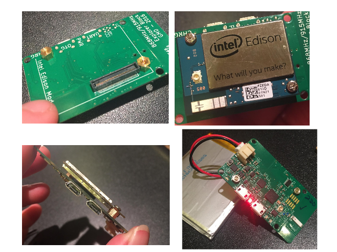
Putting the Edison and Explorer Board together
The Explorer board is where all the communications are housed for the rig, as well as the battery charger. The Edison is the mini-computer where all the OpenAPS code will be sent and used. In order for this to work, first you have to screw and connect the Edison and Explorer Board together with the nuts and bolts.
The nuts and bolts are tiny, and the spaces are a little tight. I find it really helps to use a set of tweezers and a small Phillips head screwdriver.
It’s easiest to start with the Explorer board and put on 2 nuts and gold screws (nuts on the side with most of the wiring) inside the little outline where the Edison will eventually sit. Gold screws should be placed as shown, with nuts on the backside. Then, lay the Edison board on top, aligning the screw holes. Use a small Phillips head screwdriver to tighten the screws into the gold screws beneath them. The Edison board should not wobble, and should feel secure when you are done. Attach your battery into the explorer board plug. A single red light should appear and stay lit. During the course of your OpenAPS rig use, it’s good practice to periodically check that the nuts and screws stay tightened. If they come loose, the Edison can wobble off the connection to the Explorer board and you will either get looping failures (if it’s loose) or be unable to connect to the Edison (if it comes completely off).
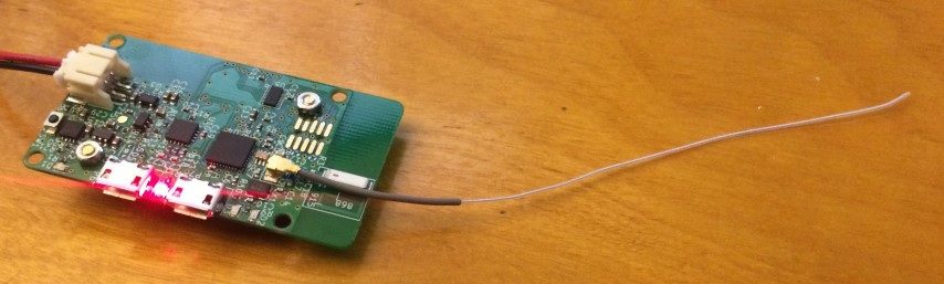
Optional: adding an antenna
If you are adding a wire whip antenna to improve the range of your rig, it simply clips on to the Explorer Board. The picture below shows the antenna clipped on and extended from the board; but you can experiment with wrapping the antenna around your rig to fit in your preferred case to see various impacts to the range.
Where is the power button?
The little black button on the end of the board near the JST connector is the power button. If you want to reboot your rig, the easiest way is to hold down the tiny power button for 10-15 seconds until the power light turns off. Wait a couple seconds and then press and hold the power button again until the light turns back on. Give the loop a couple minutes to get itself going again. Rebooting solves a majority of rig issues.
Where is the radio?
The radio and antenna are down on the end of the Explorer board where you see a little white stick (opposite end of the board from where your battery connects at the JST connector).
What the lights mean and where they are
- The LED between the two ports is the power. If this light is on, your rig is on.
- The LED in the corner is the charging indictator.
- The two next to the microUSBs (one green on the latest boards) are for the cc1110 radio chip. By default they just blink once each when you mmtune or otherwise reset it.
Charging the LiPo Battery
You can use the little white block that comes with an iPhone (or similar charger) and a microB-USB cable. The same cables you used to setup the rig and connect to the computer will work for charging, too. Either one of the USB ports on the Explorer board will work for charging. When charging is active, there is an extra red light on in the corner of the Explorer board. When charging is complete, that corner red light will turn off. It may come back on periodically as the battery “tops off”. You won’t do any damage leaving the rig plugged in for longer than the charge takes.
While the rig is plugged in for charging, the Nightscout battery pill will read approximately 65%. This is because it is reading the charging voltage rather than the battery voltage. Once you disconnect from the charger, the Nightscout battery pill will display the LiPo battery’s voltage and percent again.
Optional: increasing range for North American pumps by cutting radio trace
Another option to increase the range of your rig is to tune the existing on-board antenna by cutting it. The antenna on the Explorer Block is a hidden strip of copper underneath the green outer coating.
The antenna is labeled A1. It will have its maximum power at 868 MHz. The antenna has a line across it at one point with a label that says “915”. The antenna defaults to the 868 MHz range, which is what WW pumps use.
If you have a US pump, mmtune will run and tune to something near 916MHz. Even with the 868 MHz antenna, you should get half a dozen feet or more of range on average. If you want to boost the range of your antenna by a couple more feet, then you cut through the outer coating and the copper on that line. For North American (NA) or Canadian/Australian (CA) pumps (using the 916MHz band), you’re looking to cut near the white line that is between the 1 and the 5 in the “915.” Consider cutting on the 1-side rather than the exact spot where the white “cut” line is drawn because it is so close to the corner where the rest of the copper wire goes.
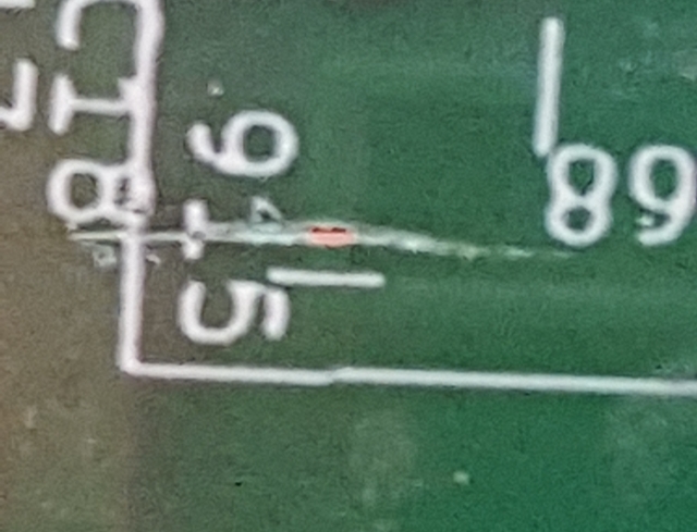
Before doing this, remember to disconnect any attached battery or power source. To make the cut, use a sharp x-acto blade to cut through the copper just beneath the green surface of board. It will take a few swipes and you’ll hear a small scraping noise when you get through the wire. Make sure you’ve cut all the way through the wire to the green circuit board material on the other side. A single clean cut is sufficient, but if the cut doesn’t look clean you could make two cuts and then dig out the circumscribed piece and then reseal the copper with nail polish. With that cut, the antenna will have maximum power near 915 MHz.
Watch this video for an example.
If you’re unsure whether you need to cut your Explorer Block’s antenna, you probably don’t. And if you decide you need slightly more range after using the Edison+Explorer rig for a few weeks, you can always come back later and do so then.